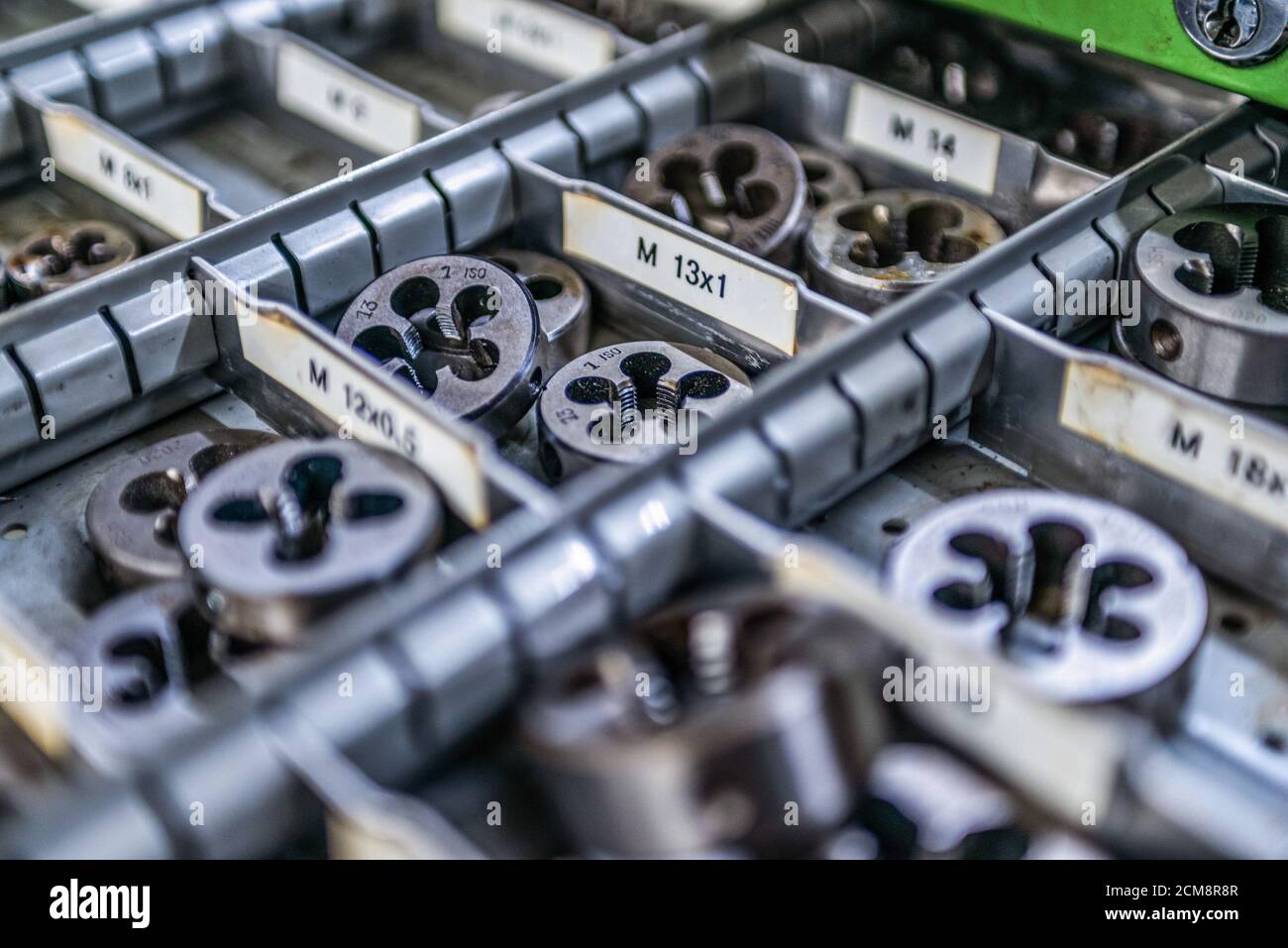
Lately I've gotten to miss that game mechanic, and there were things I wanted to do with it that I never got to do, so I'm working on a game called Energy Hook, which is swinging-and-wall-running a la Spider-Man 2 mashed up with extreme-sports-style-action a la Tony Hawk or SSX. I did a weird Kickstarter for the project, with only a $1 funding. It is possible to thread roll an internal thread, but most are cut with a tap having a progression of sharp thread cutting sections surrounding its exterior. This tap is driven into a previously drilled hole to cut a thread shape in the hole's wall as the tap moves axially. The main difference among taps is the amount of chamfer at the cutting. Commercial and mechanical contractors benefit from our pipe cutting and end preparation capabilities. Ferguson provides fire protection professionals with complete fabrication services. Whether your organization fabricates pipe in-house or not, Ferguson’s pipe fabrication, cutting and end preparation services will complement your organization. Drilling & Related Operations. Geometry of Twist drill – Shank, Neck and Drill body – Helix angle, Point angle, Flute, cutting edge, Chisel edge, Margin. Cutting conditions. Π Spindle: = Feed rate: r = f Nf. Metal Removal Rate: 4. Machining time: r m. F t A T + = For a through hole. For a blind hole. I like when you rated all the steel cutting machines based on their ability, and the best that I am seeing so far is a chop saw due to its 5-star quality of finish. My son has a school project that involves steel cutting and I have to admit that we don’t have the ideal tools to do it.

Lathe Machine:

Lathe is one of the most versatile and widely used machine tools all over the world. It is commonly known as the mother of all other machine tools. The main function of a lathe is to remove metal from a job to give it the required shape and size. The job is securely and rigidly held in the chuck or in between centers on the lathe machine and then turn it against a single-point cutting tool which will remove metal from the job in the form of chips.
For performing the various machining operations in a lathe, the job is being supported and driven by any one of the following methods.
1. Job is held and driven by chuck with the other end supported on the tailstock center.
2. Job is held between centers and driven by carriers and catch plates.
3. Job is held on a mandrel, which is supported between centers and driven by carriers and catch plates.
4. Job is held and driven by a chuck or a faceplate or an angle plate.
The above methods for holding the job can be classified under two headings namely job held between centers and job held by a chuck or any other fixture. The various important lathe operations are depicted in Fig. (a), (b) and (c).
The operations performed in a lathe can be understood by three major categories.
(a) Operations, which can be performed in a lathe either by holding the workpiece between centers or by a chuck are:
1. Straight turning –
Turning is the operation in which a cylindrical surface is produced. The workpiece is supported between centers or in any other work holding device and rotated at the desired speed. The tool is first given a depth of cut by using the cross slide motion of the carriage and then given an axial feed by hand or power. Which can be made to overlap to produce a cylindrical surface on the workpiece by adjusting the feed and having a large nose radius. Repeated cuts may be necessary to obtain a desired reduction of size. A final finishing cut may be given to the workpiece with a low depth of cut and feed but high speed to attain the desired degree of surface finish.
2. Shoulder turning
3. Taper turning –
Taper turning is the process of producing external and internal conical surfaces by combining the rotation of the job and the relative angular feed of the tool. Tapers are used on many tools and machine components for alignment and easy holding. Such as the shank of twist drills, end mills, and reamers, spindles of lathe and drilling machine.
4. Chamfering –

Chamfering is the process of beveling the extreme ends of a workpiece. It is done to remove the burrs, to protect the end of the workpiece from being damaged and to have a better look.
5. Eccentric turning –
It is a turning operation in which turning is performed at a different axis on a single setting of a job. This method of turning is generally used to produce crankshafts and camshafts.
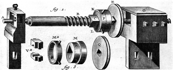
6. Thread cutting –
Cutting A Thread (project 2)the Mechanics
The process of making threads on a cylindrical job is called threading
7. Facing –
Facing is an operation used to produce a flat surface at right angles to the rotational axis of the job. In this case, the tool is fed at right angles to the job while the depth of cut is provided by the axial motion of the carriage. The job may be held in a chuck or between centers. In this center about half of the front cone is removed to give access to the tool.
8. Forming –
It is a process in which a convex, concave or any irregular surface is formed on the workpiece with the help of a forming tool. The forming tool having the required shape is used to perform forming operation.

9. Filing
10. Polishing
11. Grooving –
The process of creating a narrow slot on the workpiece is called grooving. It is also known as recessing or necking
12. Knurling –
Knurling is the process of embossing a diamond-shaped pattern on the cylindrical surface of a workpiece. Knurling is done on the workpiece so that it does not slip when held and operated by hand. The workpiece is supported in the chuck but since quite heavy forces are involved in the knurling process an additional support is generally provided at the free end with the tailstock center.
13. Spinning –
SPINNING is a method of forming sheet metal into seamless, axisymmetric shapes by a combination of rotation and force. Based on techniques used, applications, and results obtainable, the method can be divided into three categories: Manual spinning, Power spinning, Tube Spinning.
Read More: Metal Sheet Spinning process | Sheetmetal Forming
14. Spring winding
(b) Operations which are performed by holding the work by a chuck or a faceplate or an angle plate are:
1. Undercutting –
In the undercutting operation, we enlarge the diameter if done internally and decrease the diameter if done externally. It is done at the end of the hole, near the stepped shoulder of a cylindrical surface and the end of a threaded portion in the blot.
2. Parting-off –
The part is removed so that it faces the ends. For this, the parting tool is involved in slowly to make operate. To cut deeper the parting tool is pulled out and transferred to the side for the cut and to prevent the tool from breaking.
3. Internal thread cutting
4. Drilling –
The workpiece is held in a chuck or on a faceplate and the drill is held in the tailstock quill or a drill chuck held in the quill. The taper in the quill ensures that the axis of the drill is concentric with the rotational axis of the spindle. Feeding is done by movement of the tailstock quill. Reamers, counterbores and other cutting tools may also be used similarly in place of the drill.
5. Reaming –
The process of enlarging the holes to accurate sizes is called reaming. Reaming is always performed after drilling operations. It is similar to the drilling process. The reamer is held in the tailstock to carry out reaming operation.
6. Boring –
Boring is the process of enlarging a hole produced by drilling, casting, punching or forging with the help of a single point tool. Boring cannot originate a hole. In boring the job is held in a chuck or faceplate and a boring tool held on the tool post is fed into it. The operation is similar to external turning in that the feed and depth of cut are given by the longitudinal and cross-motions of the tool respectively. Since the enlarged hole is being generated with a motion of the workpiece about an axial motion of the tool.
7. Counter boring
8. Taper boring
9. Tapping
(c) Operations which are performed by using special lathe attachments are:
1. Milling –
The milling machine lathe attachment is attachable to an existing milling machine to eliminate the need for an operator owning both a milling machine and a lathe. It is designed to be mounted to the side of the milling machine and to be used without disturbing a setup in the associated vise. You can read more about milling machine attachment here.
2. Grinding –
3. Slotting –
Slotting or keyway making is the operation generally carried on a shaper machine but by using Slotting attachment, this operation is possible on lathe machine. You can read the Slotting attachment project here.
Related posts:
Mill Machining, Milling Process, Horizontal & Vertical Milling Machines
Definition
Milling is a process performed with a machine in which the cutters rotate to remove the material from the work piece present in the direction of the angle with the tool axis. With the help of the milling machines one can perform many operations and functions starting from small objects to large ones.
Milling machining is one of the very common manufacturing processes used in machinery shops and industries to manufacture high precision products and parts in different shapes and sizes.
Milling Machine
The milling machines are also known as the multi-tasking machines (MTMs) which are multi-purpose machines capable of milling and turning the materials as well. The milling machine has got the cutter installed up on it which helps in removing the material from the surface of the work piece. When the material gets cooled down then it is removed from the milling machine.
Milling Process
The milling machine involves the following processes or phases of cutting:
Milling Cutters
There are a lot of cutting tools used in the milling process. The milling cutters named end mills have special cutting surfaces on their end surfaces so that they can be placed onto the work piece by drilling. These also have extended cutting surfaces on each side for the purpose of peripheral milling. The milling cutters have small cutters at the end corners. The cutters are made from highly resistant materials that are durable and produce less friction.
Surface Finish
Any material put through the cutting area of the milling machine gets regular intervals. The side cutters have got regular ridges on them. The distance between the ridges depends on the feed rate, the diameter of the cutter and the quantity of cutting surfaces. These can be the significant variations in the height of the surfaces.
Gang Milling
This means that more than two milling cutters are involved in a setup like the horizontal milling. All the cutters perform a uniform operation or it may also be possible that the cutter may perform distinct operations. This is an important operation for producing duplicate parts.
Types of Milling Machines
The two main configurations of the milling machining operations are the types of milling machines. These are the vertical mill and the horizontal mill. They are further discussed below:
Vertical Milling Machines
The vertical mill has a vertically arranged spindle axis and rotate by staying at the same axis. The spindle can also be extended and performing functions such as drilling and cutting. Vertical mill has got two further categories as well: turret mill and bed mill.
The turret mill has got a table that moves perpendicularly and parallel to the spindle axis in order to cut the material. The spindle is, however, stationary. Two cutting methods can be performed with this by moving the knee and by lowering or raising the quill.
Cutting A Thread (project 2)the Mechanic
The other is the bed mill in which the table moves perpendicular to the axis of the spindle and the spindle moves parallel to its axis.
Horizontal Milling Machines
The horizontal mill is also the similar cutter but their cutters are placed on a horizontal arbor. A lot of horizontal mills have got rotary tables that help in milling in various angles. These tables are called the universal tables. Apart from this all the tools that are used in a vertical mill can also be used in the horizontal mill.
Cutting A Thread (project 2)the Mechanical
Sharing
Authors
Umar Farooq


